Infra-View® Infrared Boiler/Furnace Thermometer Technical Paper
The operation of a boiler and its auxiliary equipment requires the constant exercise of intuitive reasoning and sound engineering judgment. It is in operation that all of the factors that went into the design and construction of the system are put to the test. The proper instrumentation, control logic, and control system are required to assist the operation personnel in performing safe, efficient, and reliable operation. Process control, performance diagnostics, and condition monitoring are key technologies used to decrease or mitigate uncertainties. These technologies address three requirements:
- Safe and reliable operation – established by process control
- Efficiency optimization – facilitated by performance diagnostics
- Preventing process and component deterioration – detected by condition monitoring
These requirements may share the same data bias. It is in the hands of the operator to use wisdom, knowledge, and experience to achieve these requirements simultaneously. Certainly, if a common ground can be reached among these three requirements, the operator’s job will be easier and a better chance exists to achieve each singular requirement. The ideal case is that the operating control also achieves performance optimization without causing deterioration to the components. It is difficult to reach this ideal condition with current practice because each system control has its own evolution history. It will take advanced techniques, experiences, and detailed understanding of the interrelationship among these systems to reach a common goal. Certainly, it is the future challenge and focus to integrate and consolidate these procedures.
Fireside parameter Monitoring and Control
The preservation of boiler operation and performance includes meeting underlined design assumptions and process control. The boiler design involves the energy balance between the fireside and the steam side parameters. In a typical fossil power plant, there is more steam side instrumentation installed with the original control system than there is flue gas side instrumentation. However, the fireside provides the heat energy input to the boiler system and it is extremely important to control the fireside operating parameters to ensure the boiler performance. Typically, the boiler lacks fireside control. The fuel and air are mixed, combustion takes place in the burner system and the next monitoring point in the flue gas path is the boiler exit temperature. Basically, there is nothing in between. There is a simple logic to converting from a two point control, burner and boiler exit temperature, to a three point control; i.e., burner, furnace exit gas temperature (FEGT), then boiler exit temperature. This extra control point, FEGT, can have a major impact on boiler performance and reliability.
Basically, the furnace exit point separates the radiation zone from the convection pass. FEGT is one of the most important interface parameters in boiler design and operation. Typical boiler gas side design involves the following considerations:
- Input/plan areas (Btu/sq. ft-hr)
- Gas temperature entering first pendant surface over the arch
- Gas temperature leaving the furnace
- Location and quantity of furnace wall blowers
- Burner input and burner clearance
- Total heat available to burner zone (Btu/sq.ft…-hr)
The FEGT can be affected by the following operational parameters:
- Excess air level
- Furnace heat absorption rate (modified by soot blowing)
- Burner/mill selections Burner tilt
- Low NOx operations
- Coal quality
- Air in-leakage
A furnace startup probe is sometimes used to protect the superheater and reheater tubes prior to the establishment of steam flow. Unfortunately, the current startup probes can not be used for the complete flue gas temperature range. For many years the utility industry has been actively involved in developing more accurate instrumentation, analysis methods, and performance improvement techniques for the fire side parameters control. There are many techniques that can be used to obtain the FEGT on-line, i.e., direct measurement or from calculations. Direct measurement techniques can be intrusive and non-intrusive. Operators can use this information to balance combustion.
FEGT control is a critical parameter which can be used to preserve the boiler operation and performance including, emission, reliability, and safety. If FEGT deviates from the design value the following undesired condition can occur:
Increased slagging/ fouling of water walls, superheater, and economizer, and air heaters Increased corrosion rates of superheater and reheater tubes Potential of convective pass tube overheating (creep damage), requiring more attemperation Altered design conditions which are more difficult to correct by the operator Increased flue gas temperature in the boiler exit which increases heat loss and lowers efficiency FEGT provides an operational safeguard and indictor for the boiler operation.
The following influential factors will be discussed:
- Slagging and fouling control
- Soot blowing
- Coal ash corrosion control
- Superheat steam temperature control
- Low NOx firing
- Slagging and fouling control
One of the important characteristics of the fuel from a boiler design view point is the slagging and fouling control. The formation of slag deposits is caused by the deposition of molten ash on surfaces receiving heat by radiation such as the furnace and radiant sections of the supereheater. Entrained in the gas stream, molten ash particles strike the wall or tube surface becoming chilled then solidify. If slag is allowed to accumulate on the lower furnace walls, furnace exit gas temperature will rise and the slagging area is forced higher into the furnace. The effect on the furnace performance can be drastic. Proper boiler operation requires keeping the ash particles away from the walls and in suspension in the gas stream until the ash is sufficiently cool to be admitted to the convection pass.
Parameters that result in increased deposition include:
- Slagging
- Coal quality
- Improper coal fineness
- Combustion problems and poor flame stability
- Low excess O2 or O2 imbalance
- Inadequate soot-blowing
- High FEGT
- Fouling
- Coal quality
- High FEGT
- Inadequate soot blowing
Maintain the hot furnace can reduce the furnace slagging problem. Limiting FEGT to a minimum 100oF below the ash softening temperature can substantially improve the convective pass fouling problem, because the dry ash leaving the furnace will not stick to the steam tubes. If the fouling and blockage in the convective pass is reduced, the superheat soot blowing and fan power can be reduced which improves the heat rate. It also prevent soot blower erosion.
If the coal being burned is changed, the ash fusion temperature for new coals can be obtained from the laboratory test or can be provided by coal suppliers. A new FEGT limit can be established by the operator and to adjust other operational parameters to minimize the potential of slagging/ fouling. As a pre-requisite, the combustion system should be tuned to achieve the following:
- Uniform flue gas temperature and flow distribution
- Uniform distribution of excess O2
- Minimize fly ash unburned carbon content
- Minimize air heater leakage and casing air-in-leakage
- Balance secondary air and fuel distribution
- Proper primary air/fuel proportion
- Maintain required fineness and coal line temperature
Soot blowing
Ash slag and soot deposits on the tubes act as insulators that prevent heat transfer. It can also restrict the flow of flue gas. Therefore, keeping the gas side of boiler tubes clean is essential to preserve the boiler operation. Soot blowing has proved to be the most practical method of removing the deposits. Observation of the boiler for slagging and fouling patterns and for soot blower effectiveness should be made on a regular basis. A prime concern in soot blower operation is to minimize the boiler tube erosion. Soot blowers must be maintained in good operating condition. Effective soot blowing should consider the following:
- Blowing frequency
- Blowing time
- Blowing sequence
- Blowing pressure
- Nozzle position
FEGT can be used as the primary indicator to establish the scheme for automatic soot blowing or to alert the operator to start the manual soot-blowing operation. If FEGT exceeds the original design value, this indicates that the furnace is dirty and the operator should initiate the furnace soot blowing and the soot blowing should be stopped when FEGT has been reduced below the original design value. The over-blowing in the furnace is wasting the energy and can also create soot blower erosion problem in the water wall tube.
Coal ash (liquid phase) corrosion control
All bituminous coals contain enough sulfur and alkali metals to produce corrosive ash deposits, particularly those with sulfur and chlorine contents greater than 3.5% and 0.25%, respectively. Investigation has found that when dry, the sulfates formed have little corrosive activity, yet when semi-molten, they corrode most alloy steels used in superheater and reheater tube construction. Boilers operating with high furnace exit gas temperatures, which are often a direct function of water wall cleanliness, are particularly prone to coal ash corrosion from ash constituents.
Maintaining the FEGT a minimum 100 degrees F. below the ash softening temperature can reduce the potential of superheater coal ash corrosion for high sulfur coal firing, because the dry ash entering the convective pass will not adhere to the steam tubes.
Superheat steam temperature control
For the tangentially fired furnace, the burner tilts are typically used as one of the methods to control the final steam temperature. The use of tilting up option to achieve desired steam temperatures should be applied at low and intermediate loads only. Burner tilts position should be horizontal or angled slightly downward at high loads. The reason for tilts down or horizontally is to increase residence time for complete combustion. The burner tilts up condition may increase FEGT, which can increase the potential of slagging and fouling problems as discussed previously. If the final steam temperature can not be reached, other options such as increase excess air should be considered in conjunction with the burner tilting to maintain FEGT within the allowable limit.
Low NOx firing
Wall fired low NOx burners normally result in longer flames and higher unburned carbon content. The potential of secondary combustion could become more intense and increase fouling and slagging of the convection pass and air heaters. The under-stoichiometric combustion, typically used in the low NOx firing, will result in starvation of oxygen in the furnace areas. This can creates areas of reducing atmosphere, which can accelerate fireside wastage of water wall tubes. Delayed combustion or secondary combustion sometimes produce high FEGT. These high temperatures can cause overheating of superheater and reheater tubes. It is essential for the operator to maintain the original design FEGT to minimize other side effects. Otherwise tradeoffs are required and comprise the multiple system objectives.
Using the Infra-View®Infrared Thermometers for Furnace Gas Exit Temperature Measurement
The furnace exit gas temperature (FEGT) in a utility boiler is a critical parameter which requires monitoring during boiler start-up and on-line operation. Start-up FEGTs must be controlled so as not to exceed allowable superheater tube metal temperatures. Many fossil plants use air-cooled probes, which must be retracted when temperatures reach 1,000 degrees F. Maintaining the FEGT within the design limit during the normal operation can ensure boiler operability, thermal performance and boiler reliability. The problem in the past is the lack of on-line instrumentation to measure the high flue gas temperature. Water-cooled HVT probes have been used for many years to measure gas temperature above 1,000 degrees F. Because of the probe length and weight limitations, HVT is used primarily for testing purposes and not for continuous operation.
An infrared system has been developed to measure the flue gas temperature. The patented system has the trade name of Infra-View®Infrared Thermometers. The infrared Infra-View®sensor detects the heated CO2 gas created in a boiler or furnace as a product of the combustion process when fossil fuels are burned. The infrared spectral response of the Infra-View®sensor is preset specifically to detect CO2 infrared energy by using a thin film thermopile with a spectra filter designed to block out all other wavelengths of infrared emissions. Since the Infra-View detector is sensitive to only the hot CO2 gas spectrum, it can measure temperature of the CO2 gas directly within the field of view.
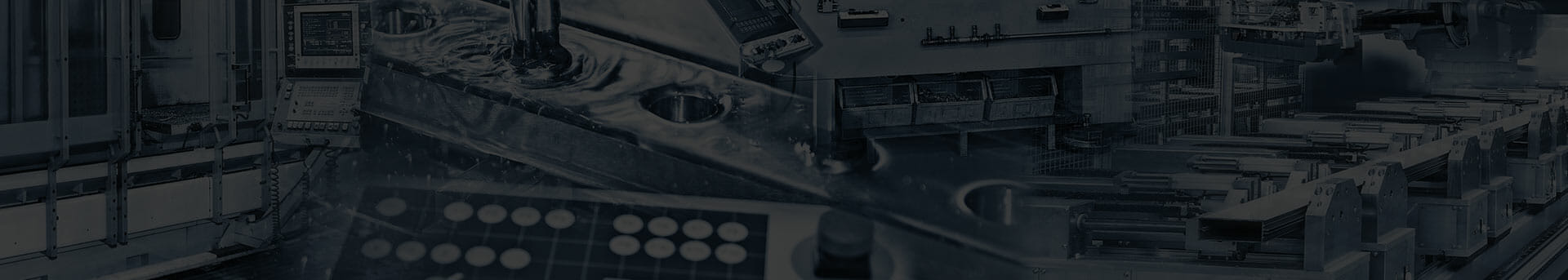
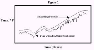
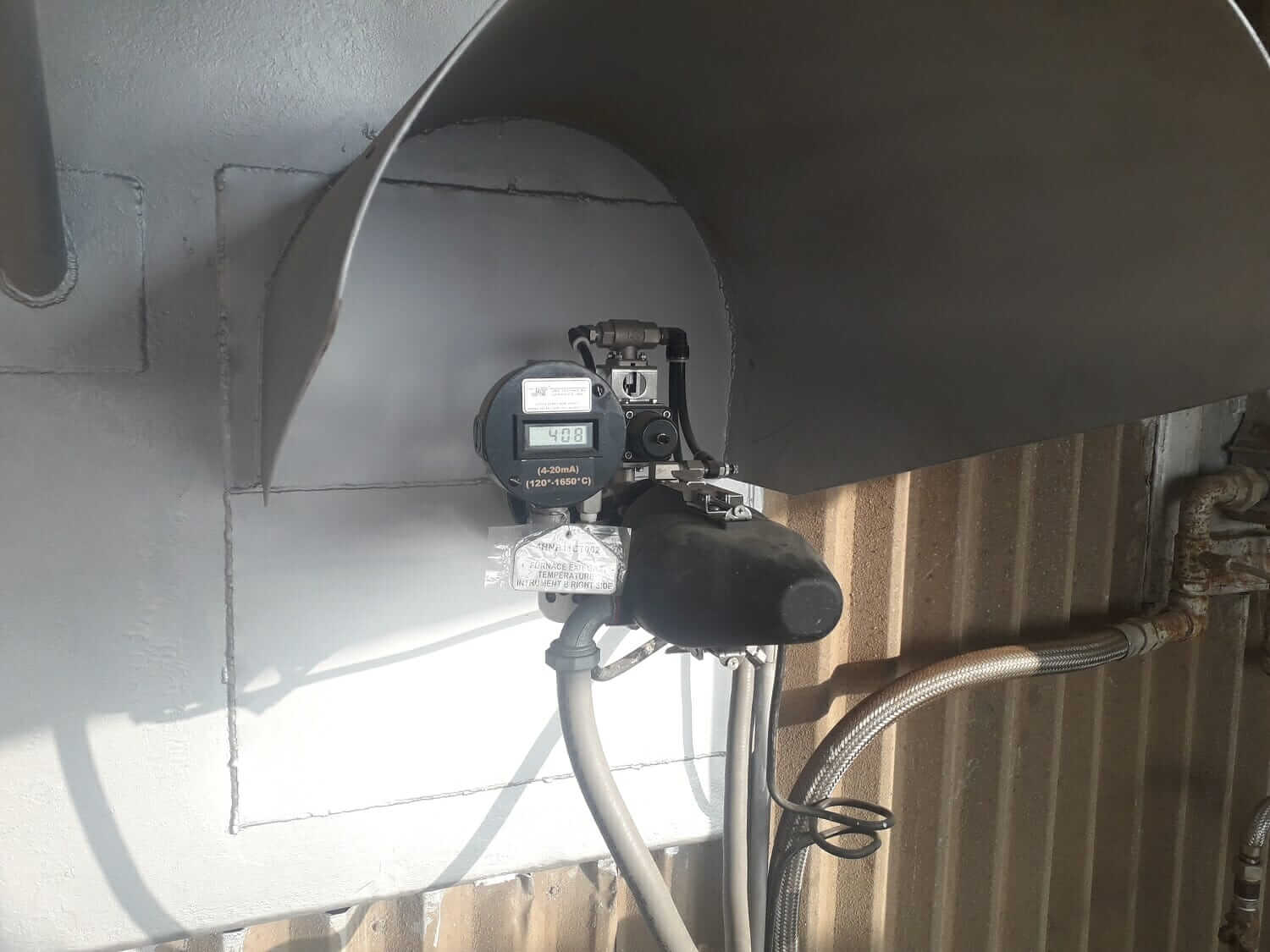
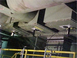
Infra-View®Infrared Thermometers are remote sensing infrared detectors that are permanently flange mounted on any port, door or penetration into the boiler or furnace. It is a lightweight device and can also be used as a portable system for testing purposes. The Infra-View®patented design is supplied with a rugged protective-cooling jacket that is factory assembled and pre-piped with an air cooler, purging and filtering system designed to work in most severe service environments. Customer supplied compressed air and two wire shielded signal cable is all that is necessary for operation when integrated in a 4-20mA signal loop supplied from a DCS, digital or analog recording device. The Infra-View®infrared “non-contact” sensors monitors flue gas temperatures in the boiler or furnace ranging from 250 degrees F. (120° C) to 3000 degrees F. (1,650° C). Higher end temperature measurements are also available.
Infra-View® “Smart Sensor” Technology and Operation
The Infra-View boiler thermometer is a passive infrared detector that senses boiler gas temperature from 250ºF to 3000º F when integrated in a 4 – 20 mA signal loop from any digital or analog device. The heated CO2 gas is at a molecular level of excitation that becomes detectable through this method of infrared remote sensing. As the temperature in the boiler increases, CO2 gas excitation increases concomitantly in this infrared spectrum.
The proprietary infrared spectral response of the Infra-View thermometer is pre-set specifically to detect infrared emissions from hot CO2 gas. This is accomplished by filtering out all other wavelengths of infrared energy. Modern infrared thermometry has advanced significantly with the use of “selective filtering” of the incoming infrared signal. Specifically, selected narrow band spectral responses are necessary in order to see through atmospheric interferences in the sight path, to obtain a measurement of gas or other substance which is transparent to a broad band of infrared energy.
Infrared radiation is observed as emitted from excited molecules of gases. Many of the energy transitions which take place in gases excited thermally or electrically result in radiation emission in the infrared region. Gaseous emission differs in character from solid emission in that the former consists of discrete spectrum lines or bands, with significant discontinuities, while the latter shows a continuous distribution of energy throughout a broad band spectrum.” Gases such as CO and CO2 exhibit a strong but narrow infrared spectral response that can be detected with sensitive infrared sensors utilizing the specific spectral filter.
Since CO2 gas is a by-product of the combustion of all fossil fuels, its unique spectral response was selected because of its applicability to all boilers and furnaces regardless of the fuel burned. With a concentrations of CO2 gas typically found in fossil fuel burning utility and industrial boilers, there is a high enough level (10 – 12%) to reach a threshold of detection where the Infra-View sensor can measure the average or peak temperature directly within the field of view of the instrument. Because the Infra-ViewÒ “sees” the CO2 gas within the boiler as semi-transparent or opaque medium, within the conical field of view (30:1) the largest volume of gas molecules are oriented farthest away from the sensor. Hotter gases, because of the selective spectral filter, are favored over the cooler gases located nearer the sensor comprising a smaller volume in the field of view. As a consequence, the Infra-ViewÒ will sense heated flue gas in the boiler yielding a temperature reading that is indicative of the overall boiler environment. Secondly, the quick response time (100 msec.) when averaged over say, 10 seconds (100 readings in all) generates a representative temperature reading of the dynamic upward flow of heated gases past the sensor posting the processed data in a time vs. temperature relationship.
The Infra-View®”smart” sensor can be programmed to measure the average or peak temperature directly within the field of view of the instrument. The Infra-View® Boiler Thermometer will measure gas temperature across the boiler or furnace, however, when the line of sight is directed at the fireball, the Infra-View®will only measure the temperature of the fireball flame due to extremely high concentration of CO2 gas generated there. Average temperature readings are particularly useful in the superheat, reheat and convection passes because boiler flue gasses tend to be vertically stratified in terms of temperature. As a consequence, the temperature reading will be the average value of all the vertical stacked gas temperatures in the field of view of the Infra-View®. This is indeed a more useful value, when compared to measuring a point source at a given depth with say, an HVT probe. Point source measurements are certainly not indicative of the overall temperature profile in the boiler. Peak temperature readings are most applicable for start-up control.
Ostensibly, average readings are arithmetic mean value of the peak (highest) and valley (lowest) reading processed over programmed duration in the “smart sensor”. Peak readings are actually a peak hold reading that stores the highest temperature over a predicted time interval or duration. Should the “smart sensor” measure a temperature higher than the one currently displayed, it immediately updates the display and starts a new time interval. Should the “smart sensor’ see no temperature above the one presently displayed, it will hold this value until the duration expires.
Infra-View® Boiler Control Functions
The Infra-View® Boiler Thermometer “smart sensor” can provide a flue gas temperature reading with an accuracy of + 1% of reading. Primary signal processing occurs within the Infra-View® Boiler “smart sensor”. For average and peak readings based on a 100 msec. response time, a temporal component can be programmed, by processing the output signal posting time from 1 to 60 seconds.
Through empirical testing, we have discerned that the Infra-View® Boiler Thermometers most applicable flue gas temperature readings can be acquired through the use of the Peak Hold “smart sensor” function combined with additional signal conditioning within a distributed control system (DCS).
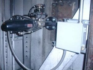
Infra-View®peak readings with a 10 second hold, are transmitted to the DCS via a 4 – 20 mA analog output. Within the DCS, these outputs are further digitally filtered or conditioned with internally stored algorithms. The two most germane algorithms are a smoothed value transform (smoothing function) or the running average transform (run average mode).
Smoothing Function: Smoothing of an analog input consists of giving the most weight to the most recent sample and the diminishing weight to all preceding readings. The relative weight given to the most recent value is determined by the smoothing time constant specified for input filtering.
Run Average Mode: The analog input is sampled periodically as specified by the user from the Number of Units and the Units of Time Fields. An average reading of all data is posted based on first in last out data stream.
A conditioned output signal is displayed in Figure 1 demonstrating real time temperature data from the Infra-View® Boiler Thermometer fed into a DCS and filtered in order to generate a “smooth” temperature curve that can be utilized for control.
These “smoothed” output signals can then be utilized for automation of control valve operation during start up; soot blower control; ash fusion control; superheater high temperature annunciation and numerous other functions such as SNCR enhancer addition which is extremely temperature dependent.
Infra-View® Boiler Thermometer Applications
-
- Startup temperature control
- The system can be used to monitor flue gas temperature ramp from 250 degrees F. to 1200 degrees F. for boiler startup when bring the steam turbine online. The utility boilers normally are equipped with retractable temperature probes. The Infra-View sensor can be used to replace retractable system and perform startup and normal operation flue gas temperature The Infra-View system is less cost and easy to use and maintain.
- Startup temperature control
-
- Soot blower control
- The real-time FEGT data is transmitted to control room. The operator can use the date to establish the scheme for automatic soot blowing which includes blowing time, sequence, and frequency. Or it can used to alert the operator to start the manual soot blowing operation. For example, if FEGT exceeds the original design value, this indicates that the furnace is dirty and the operator should initiate the furnace soot blowing and the soot blowing should be stopped when FEGT has been reduced below the original design value. The over-blowing in the furnace is wasting the energy and can also create soot blower erosion problem in the water wall tube. Monitoring boiler gas temperature for comparison to steam outlet temperature can also be used for determining soot blower activation. A software system is available to record time vs. gas temperature histories.
- Soot blower control
-
- Slagging/ Fouling control and superheater protection
- FEGT should be maintained below the ash fusion temperature to minimize the slagging and fouling. Operating FEGT above the design value can alter the design condition and cause long-term overheating of the convective pass pressure components. If FEGT exceeds the desired value, the operator can exercise other options to reduce it, e.g., soot blowing, altering excess air, change burner patterns and tilts, flame length, and others. The automatic control schematic can also be established to optimize the procedure.
- Slagging/ Fouling control and superheater protection
-
- Low NOx application
- The system can be used to measure flue gas temperature “window” set point between 1,600 degrees F. and 2100 degrees F. for injection urea or ammonia in Selective Noncatalytic Reduction Systems for maximizing NOx removal efficiency.
- Low NOx application
-
- Fluidized bed boilers
- The system can be used to determine optimal temperature for pulverized limestone injection on flue gas desulfurization systems and general operating conditions.
- Fluidized bed boilers
-
- Boiler Performance Monitoring
- Multiple sensors can be installed in separate sections along the flue gas pass. With the assistance of computer software the complete boiler temperature balance can be obtained and the data can be used for in-process monitoring and control of the boiler performance.
- Boiler Performance Monitoring
-
- Fireball Centering for Tangentially-Fired boiler
- Two or more sensors can be installed in the tangentially-fired furnace to identify fireball centering condition and proper actions can be taken to correct this combustion problem.
- Fireball Centering for Tangentially-Fired boiler
-
- Waste/Refuse Incinerators:
- This system has been used to monitor compliance temperatures for incineration of toxic wastes at 1800 degrees F. Infra-View can be certified to NIST standards.
- Waste/Refuse Incinerators:
-
- Monitor Black Liquor Temperatures
- The temperature of the gas in the recovery boiler is critical to its efficient operation and performance. Excessive temperatures can cause excessive odor or cindering of black liquor particles and can fuse to superheat and reheat tubes thereby decreasing the heat rate of the boiler from plugging of heat transfer surfaces.
- Monitor Black Liquor Temperatures
Conclusion
The preservation of boiler operation and performance requires proper fireside operating fireside control. Basically, the existing boilers are lacking of proper fireside control. The fuel and air are mixed, combustion takes place in the burner system and the next monitoring point in the flue gas path is the boiler exit temperature. It is recommended that the process be converted from two point control, burner and boiler exit temperature to three point control; i.e., burner, FEGT, then boiler exit temperature. This extra control point,, FEGT, can have a major impact on boiler performance and reliability. The Infra-view system provides wide range flue gas temperature measurement and is a low cost effect instrumentation to measure the FEGT on-line. The system has been demonstrated successfully in more than 400 sites to provide real-time information for boiler operation, performance, and reliability improvement.
Note: Technical authors and references available upon formal written request.
Use our Pyrometer Selector to find the right solution for your temperature monitoring needs and place a request for quote.
Click Here for Pyrometer Selector
Infra-View® Infrared Boiler Thermometer Instructions
Click one of the links below to see user instructions related to the Infra-View® Infrared Boiler/Furnace Thermometer:
Need an Infrared Boiler/Furnace Thermometer?
Check out our Infra-View® Infrared Boiler/Furnace Thermometer! Comes with a durable and functional cooling jacket for easy mounting and installation. Read temperatures up to 4,500 deg F with low maintenance due to passive detection method from outside the boiler wall.
- Medium: Combustion/Flue Gases
- Temperature Range: Up to 4,500 deg F
- Low Maintenance, Up to 25 year lifespan
Read More
Need a Portable Infrared Boiler/Furnace Thermometer?
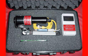
Check out our Infra-View® Handheld Boiler/Furnace Thermometer! A basic sensor with carrying case, tripod, mounting bracket, and local readout.
- Medium: Combustion/Flue Gases
- Pressure: Up to 4,500 deg F
- Easy to Install
Read More
Need an Infrared Generator Buss Duct Thermometer?
Check out our Infra-View® Generator Buss Duct Thermometer! Comes with a simple mounting ring for easy install, place one on each phase to protect buss work from overheating.
- Medium: Ductwork Material
- Temperature Range: 0 to 1,000 deg F
- Great for System Evaluation